Instrument Constant Voltage Regulator Repair
Have all your instruments started playing up, or stopped working altogether?
Chances are your CVR is the culprit, but don't worry, you can repair it for $5!
This mod has been performed successfully by a couple of our members, but I'm not sure who takes the credit for the original idea.
If you know, let me know and I will add the credit to this article.
Parts Required:
- 7805 Voltage Regulator ($1.85 at Jaycar)
- Heatsink compound ($3.95 at Jaycar)
- Small amount of wire
- Solder
- Small screw/nut for mounting the 7805
Tools Required:
- Screw driver
- Pliers
- Wire strippers
- Soldering Iron
The Constant Voltage Regulator is most often the problem when people have issues with their gauges. Particularly if all of the gauges are playing up.


The good news is, that you can repair the CVR using a solid state (electronic) voltage regulator that should last the life of the vehicle.
The CVR is located on the back of the instrument cluster and will probably look something like the ones below. On the left is a 69 up unit, and on the right is 65-68.
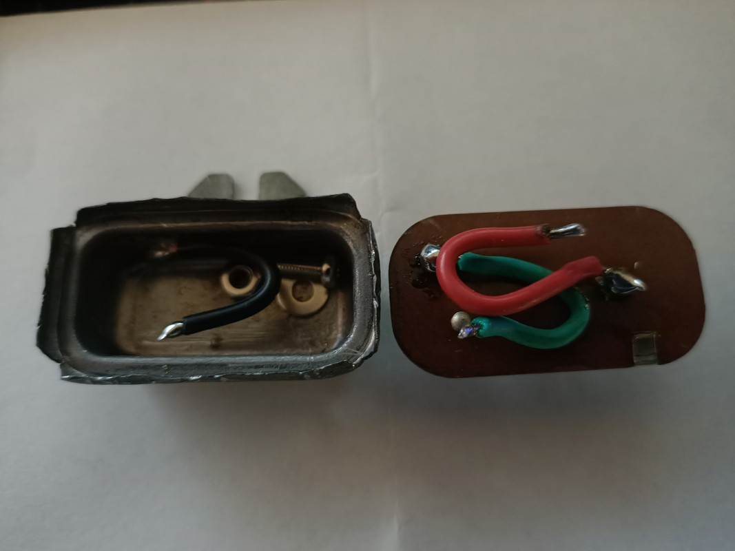
The first thing to be done is to disassemble the original CVR.
Use a flat blade screw driver to pry up the metal tabs on the bottom of the unit. You can then use the pliers to bend them out further. Careful use of side cutters also works.
Once apart, it will look something like this:
Remove the metal strips, leaving just the tabs. You will solder the wires to the remaining tabs.
First, solder wires to the regulator. Ensure you use just enough wire so it will all fit in the original case.
The 7805 pinout is below.
Solder a wire from Pin1 to the spade connector on the CVR cover labelled IGN. This is your 12V input.
Solder a wire from Pin3 to the other spade connector on the CVR cover. This is the 5V output to your gauges.
The LM7805 should be grounded through it's body, so you could just cut off Pin2, but I would connect a wire to it anyway and attach it to the body of the enclosure.
You could crimp a round connector to the wire and attach it to the screw used in the next step. There may also be another tab that attaches to ground that you can solder the wire to.
It should look something like this:
Work out where the LM7805 will be mounted in the case and drill a hole in the case. Mount the LM7805 to the case using a small bolt/nut ensuring that you use a small amount of heatsink paste between the enclosure and LM7805. Attach the wire from Pin2 to the bolt as well if you used that method.
Place the cover back on the enclosure and crimp the tabs back over it.
Test!
Job done!