boofhead wrote:Correct - as Hybrid said 30ma low current to drive the relay so it switches the high current side. Same principle in place for fuel pump and FIdle.
ooo speaking of FIDLE.. you just raised an eyebrow for me..
so the FIDLE is a trigger wire too.. meaning the FIDLE plug i have (2 wires) needs to also be hooked up to a relay? and wired in the similar principal as the FP and the Fan relays?
I'm using a ford PWM idle control valve, so my fidle wire sends a PWM (varying) signal.
If you are just wanting to use fast idle when the engine is cold, you just need on/off solenoid, so you could use a relay.
The microsquirt can control PWM straight off the board. If you wanted PWM, you'd have to check if the fidle transistor on the board can drive it directly. Sometimes you need to upgrade it.
hybrid wrote:That depends on the type of fidle you use.
I'm using a ford PWM idle control valve, so my fidle wire sends a PWM (varying) signal.
If you are just wanting to use fast idle when the engine is cold, you just need on/off solenoid, so you could use a relay.
The microsquirt can control PWM straight off the board. If you wanted PWM, you'd have to check if the fidle transistor on the board can drive it directly. Sometimes you need to upgrade it.
ok i dont know the difference between the 2 or what looks like what.
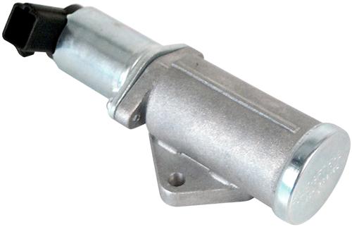
this is what i have hanging on the side of my throttle body..
so what does that mean f idle or pwm? i think its Fidle isnt it? or have i got my wires (no pun) wrong
Generic fast idle is just a valve that opens a set amount to idle up the car while it's cold. It is not variable - it's on/off.
PWM (Pulse Width Modulation) is a variable valve.
The higher the pulse width that is sent to the valve, the more it opens. So it's an IAC valve, but not a stepper motor.
Your one pictured looks like PWM. How many pins does it have? I had a 2-wire ford PWM, but could not get it to work properly, so I switched to a bosche 3 pin valve and it works great.
You'll need to work out the settings that it needs to open and close.
hybrid wrote:Generic fast idle is just a valve that opens a set amount to idle up the car while it's cold. It is not variable - it's on/off.
PWM (Pulse Width Modulation) is a variable valve.
The higher the pulse width that is sent to the valve, the more it opens. So it's an IAC valve, but not a stepper motor.
Your one pictured looks like PWM. How many pins does it have? I had a 2-wire ford PWM, but could not get it to work properly, so I switched to a bosche 3 pin valve and it works great.
You'll need to work out the settings that it needs to open and close.
The v3.57 board's major claim to fame is it's 'surface mount (SMT)' design. Otherwise it is almost identical to the v3.0 board and the above information on the v3.0 board fully applies. The only other major differences are:
A) the addition of a PWM capable idle control transistor allowing control of a PWM idle valve or a standard on/off type FIDLE valve without need for modification. This was a common modification applied to the v3.0 board and is no longer needed on the v3.57.
B) the addition of a DB15 connector next to the DB9. By default this doesn't do anything, but is there to allow for extra I/O for modifications. It takes the place of the externally viewable LEDs, which are now internally surface mounted on the PCB.
C) Several signal pads have been added making common modifications easier.
D) The prototype area was sacrificed (removed) to make all of the above possible.
Looks like you can drive PWM out of the box, so you're good to go.
Hybrid is correct. Having said that your relay board already has the fIdle relay built into it. So you get it for free. First relay is the main relay, second is the fuel pump and the third is the fIdle relay. See:
Note: There is a jumper for 12 V or ground operation for the fIdle so I am not sure how yours is set up. Obviously, you can choose not to use the Relay at all and redirect its use to the as the Fan relay.
ok thats what i wasnt sure. if i had to add a fuel pump relay.. but you are saying and according to the diagram the middle relay IS a fuel pump relay ..
SOOOOOO that means the FP port on the relay board ISNT a trigger wire? its a main feed wire? is that right..
im continually amazed at the megasquirt and its capabilities.. i thought it was a more simple ecu but its not .. theres LOTS of capabilities and functions that im learning!
'You can never test fire too many times.' - Hybrid
Note that the FIdle circuit on the relay board is limited to 1.1 Amps by the polyfuse. The relay is capable of handling much more current, but the traces on the relay board are NOT. If you wish to use the FIdle relay, do not use it to drive a device that requires more than 1.1 Amps (though you can use it to drive a second relay and control much more current - like an electric fan relay)
so even though a relay is in use on the relay board you can use it to drive anothe relay
'You can never test fire too many times.' - Hybrid